|
After the oscillator by the integrated 555, present in this same section
( astable multivibrator), object of the experiment
illustrated here, is an oscillator controlled by a quartz crystal. The quartz crystal, by its nature, only
oscillates at one characteristic frequency that depends on its physical constitution, mainly on its thickness.
You use quartz crystal when you want to have one higher frequency precision, therefore free from variations
introduced by temperature or voltage variation and / or other factors. Digital watches modern are largely
controlled by a quartz crystal resonating at the characteristic frequency of 32,768 Hz. By halving this
typical frequency 15 times, you get exactly one pulse per second to be applied to the digital clock counters.
There are several ways to get a quartz controlled oscillator, the simplest is to use 2 ports hex inverters
as we have already seen in the page dedicated to that type of oscillator
Oscillator with quartz controlled Hex Inverter. Since the present oscillator was conceived to
constitute the time base of a digital clock, we sought an integrated which enclosed itself in addition to the
oscillator function, also the divider function. The choice fell on an integrated belonging to the CMOS logic
family of the 4000 series of the CD4060 or its equivalent (74HC4060, MMC4060, MC14060). The integrated contains
within it a section used to obtain the oscillator controlled by the quartz crystal and 14 stages of flip-flops
circuits by which the oscillation frequency is divided up to obtain a pulse every 2 seconds. It goes without
saying, that a further stage is needed to obtain the fateful 1Hz to be applied to the clock counters.

Fig. 2 - CD4060 pins
|
For CD4060 Datasheet

|
However, a digital clock, at least for the first start, needs to be set or better synchronized to the current
time, so it is not enough. have only the frequency of 1Hz for the counters, but also a higher frequency in order
to quickly synchronize the clock. In the block diagram below, the frequencies available on the various pins of
the integrated are visible.

Fig. 3
|
Finally, in figure 4, the wiring diagram of what has been described up to now with reported values of the
passive components. Yes remember that the black point identifies pin 1 of the integrated circuit seen from above.
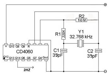
Fig. 4
|

Fig. 5
|
If you want to test the oscillator to verify its correct functioning, you can use our experimental base.
The simplest way to check its operation is to drive one or more LEDs at the lowest frequencies. Enter the
positive terminal of the LED at the 2Hz output (pin 3 of the integrated) and connect, by means of a 120 Ohm
resistor, the negative terminal of the same to the ground of the circuit. The LED will blink 2 times every
second, while connecting it to pin 2, this will flash at a rate of 4 flashes per second.
To begin the connection of the components, we start by arranging the integrated over the
two half-bases. It fits the quartz in the most convenient position relative to the ground of the circuit,
then connect the capacitors between the terminals of the quartz and the mass. We move on to connect the
resistors, then connect the power supply terminals of the integrated, not forgetting to put a ground the
RESET terminal. The positive terminal of an LED is connected to the 2 Hz output of the CD4060, pin 3, and
through a resistor 120 Ohm, to limit absorption, to the circuit ground. You connect the positive and negative
of the breadboard to the power supply afterwards have selected an output voltage of 5 V, and turn on the power
supply. Below is the complete wiring diagram of the base useful times for the realization of a digital clock
with the complete frequency range.

complete circuit
Who had built the digital clock
digital clock illustrated in the section projects can use this oscillator with very few modifications.
In the first place the integrated 555 used as a time base is removed, then after having made the quartz controlled
oscillator on a suitable base, it is placed in the immediate vicinity of the base of the 555 mentioned above and
connects to pin 3 (now free) the frequency of 256 Hz from the appropriate output of the CD4060. I remember that
the frequency of 256 Hz was divided by the TC4520 to derive in addition to the 1Hz time base, also the frequency
for setting the time and the frequency for the multiplexer operation for energy saving.
|


